


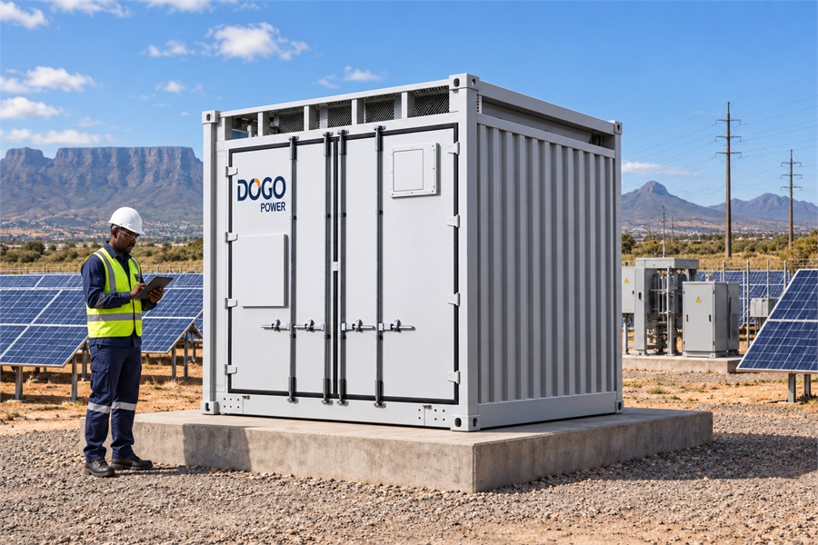
What manages the flow of electricity between a battery energy storage system and the grid? A power conversion system (PCS) performs that essential job. It converts DC power from the battery into AC power for the grid or local loads, converts AC power back into DC during charging, and regulates how the energy storage system responds to changing electrical conditions.
For modern energy storage, PCS capability extends beyond basic charging and discharging. A grid-forming PCS can help establish a local voltage and frequency reference, making it relevant to weak-grid, off-grid, microgrid, mining, island, and renewable-dominated applications. The PCS role should be evaluated through the complete energy storage system, including battery limits, plant controls, protection, and the operating conditions the project must handle.
What Is a Power Conversion System (PCS)?
A power conversion system is the bidirectional electrical interface between the DC battery system and the AC network. It manages the conversion, control, and protection required for energy to move safely in both directions.
The basic power path is:
Typical AC-coupled configuration
Battery cells and racks ↔ DC bus ↔ PCS ↔ AC bus ↔ loads, PV, generators, or the utility grid
In an AC-coupled system, when surplus electricity is available, the PCS converts AC power into DC power and controls the charging process. When the site needs energy, the PCS converts stored DC power into AC power for local consumption or grid export. The U.S. Department of Energy describes this two-way operation as a core function of bidirectional power electronics in battery storage systems.
In this AC-coupled configuration, PV connects to the AC bus through a PV inverter. In a DC-coupled PV-plus-storage system, PV can charge the battery through a DC/DC converter without first converting that energy to AC.
The PCS also monitors electrical conditions and exchanges information with other system controls. Its operating limits are affected by the battery voltage range, current, temperature, state of charge, and state of health. The Battery Management System (BMS) communicates battery limits to help keep charging and discharging within safe boundaries.
PCS and battery inverter are sometimes used as equivalent terms, but equipment boundaries vary between suppliers. A project specification should confirm whether the PCS package includes the bidirectional inverter, transformer, switchgear, cooling, protection, communication interfaces, and plant-level controls, or whether those items are supplied separately.
Functions of a Power Conversion System in a BESS
Inside a Battery Energy Storage System (BESS), the PCS is responsible for more than changing electricity from one form to another. Its control functions influence energy efficiency, power quality, grid interaction, and the system’s ability to support stable operation.
Bidirectional Power Conversion
The primary function of a PCS is bidirectional DC/AC conversion. During charging, it receives an AC power command and regulates the DC current sent to the battery. During discharge, it controls the conversion of DC battery energy into AC power for the grid or connected loads.
Bidirectional control gives a BESS operational flexibility. The same system can store excess PV generation, discharge during peak demand, support backup loads, or respond to a grid dispatch signal. The actual power available at any moment depends on the PCS rating, battery condition, thermal limits, operating reserve, and project control strategy.
Frequency and Voltage Regulation
A PCS can adjust active power in response to frequency changes and manage reactive power or voltage within its operating envelope. These functions allow energy storage to support power quality and respond to grid-service requirements.
Frequency regulation requires more than a fast converter. The battery must have sufficient available energy and reserve, the control system must receive an appropriate command, and the project must comply with the applicable grid rules. Reactive-power capability is also shaped by the PCS design, AC voltage, current limits, transformer configuration, and interconnection requirements.
Energy Conversion Efficiency Optimization
PCS efficiency directly affects how much electricity a BESS can deliver and the project’s financial performance. Power-electronics design, operating point, thermal management, auxiliary consumption, and control algorithms all influence conversion losses.
Evaluate efficiency under the conditions the system will face in daily operation. Review charging and discharging power, partial-load performance, ambient temperature, auxiliary consumption, cooling demand, battery degradation, and the selected grid-forming or grid-following mode. Use round-trip efficiency across the complete battery-to-grid energy path as the main comparison metric. Peak PCS efficiency represents only one part of the overall result.
Grid-Forming Control and Weak-Grid Support
Grid-forming capability is the major step beyond conventional grid-following operation. A grid-following PCS measures an existing grid reference and injects current according to its power commands. A grid-forming PCS is designed to establish an AC-side voltage and frequency reference, then regulate power around that reference.
In a weak-grid or islanded project, the key question is whether the PCS can maintain a stable voltage and frequency reference without relying on a strong external grid. A grid-forming PCS may support microgrid operation, coordinate with PV and wind converters, respond to load changes, and help manage transitions between grid-connected and off-grid modes. The National Renewable Energy Laboratory explains that grid-forming controls are intended to operate more flexibly in hybrid and inverter-dominated power systems.
Grid-forming is not a universal performance guarantee. The required behavior depends on the converter controls, battery reserve, SOC range, network strength, protection settings, load characteristics, renewable generation, and commissioning sequence. If a project requires black start, fault ride-through, virtual inertia, damping, seamless transfer, or resynchronization, each capability should be specified and verified separately.
Grid Integration and System Communication
The PCS acts as an electrical and communications interface between the BESS and the wider energy system. It receives commands from the Power Management System (PMS) or Energy Management System (EMS), exchanges operating limits with the BMS, and responds to grid or site conditions.
The EMS usually manages longer-horizon decisions such as PV and load forecasting, tariff-based scheduling, energy shifting, and asset monitoring. The PMS coordinates power at the plant level, while the PCS executes fast electrical control. When these layers are coordinated, the system can balance immediate stability requirements with longer-term energy and operating objectives.
How DoGo Power Integrates PCS into Grid-Forming ESS
Our advantage lies in connecting PCS hardware with grid-forming control, system simulation, project delivery, and long-term operation. The PCS is not treated as an isolated converter. It works within a complete architecture designed for weak-grid, off-grid, renewable, commercial, industrial, and utility-scale applications.
4S Architecture for Coordinated Grid-Forming Control
When battery limits, plant controls, and energy dispatch are managed separately, it becomes harder to maintain a fast and stable system response. We developed 4S Grid-Forming Technology to bring the Energy Management System (EMS), Battery Management System (BMS), Power Management System (PMS), and Power Conversion System (PCS) together in one software-defined energy architecture.
The PCS responds to changes in voltage and frequency. The BMS keeps the battery within safe operating limits, while the PMS coordinates power flows and the EMS manages dispatch and energy use. By sharing operating data through a closed control loop, these systems work together to deliver fast response, protect battery capability, and give operators better control over plant performance and energy costs.
Commercial and Industrial Grid-Forming Applications
Commercial and industrial sites often deal with sudden load changes, motor starting, power-quality issues, high peak demand, and interruptions in grid supply. Our C&I Grid-Forming Energy Storage Solution combines grid-forming energy storage, PV systems, and intelligent energy management to address these operating challenges. It supports self-consumption, load shifting, demand management, backup power, and renewable-energy coordination in both grid-connected and off-grid modes.
A system that looks suitable on paper may not perform well under real site conditions. We therefore consider the site's load profile, motor-starting requirements, critical loads, power-quality needs, and grid-to-off-grid transitions before deciding on the storage configuration. Our support covers system design, grid-level microgrid simulation, delivery, full-process monitoring, and operation and maintenance.
When the site experiences a rapid load change or a grid disturbance, fast voltage and frequency control helps maintain stable operation. Remote monitoring and alarm management give operators a clearer view of system status, while coordinated PV-storage control helps the site make better use of renewable power. The result is a system built around the site's actual operating needs, rather than a standard PCS rating.
Utility-Scale Multi-Timescale Control
Renewable power plants and large-scale storage projects face changing output, limited regulation capacity, curtailment, and growing requirements for grid support. Our Utility-Scale GFM Smart BESS Solution coordinates grid-forming storage with PV and other generation assets. It supports plant-level power smoothing, renewable fluctuation suppression, energy shifting, voltage and frequency support, and more flexible dispatch.
Different grid events require different response speeds. The millisecond-level grid-forming layer handles rapid voltage and frequency changes. A higher-level coordination layer manages emergency response, grid synchronization, and fast black start. At the dispatch level, minute-scale control coordinates PV, storage, and diesel generation to support efficient plant operation.
Large projects also need to identify control and stability issues before the system is delivered. We support developers with system design, electromechanical and electromagnetic transient simulation, hardware-in-the-loop testing, delivery, and full-process monitoring. By linking PCS response with PMS coordination and EMS optimization, we help project teams evaluate both short-term grid stability and long-term plant operation.
Integrated Support for Weak-Grid and Off-Grid Projects
Weak-grid and off-grid projects often face unstable voltage, fluctuating renewable output, sudden load changes, diesel dependence, and strict power-continuity requirements. These conditions call for coordinated control across the PCS, battery, generation sources, and plant systems.
To address these needs, we combine GFM ESS products with EMS/PMS coordinated control, system simulation, project design, commissioning support, and operation services. Before deployment, project teams can assess grid strength, load steps, PV output, diesel coordination, protection settings, islanding sequences, and black-start requirements. This provides a clearer basis for system configuration and project delivery.
How Our Grid-Forming ESS Helps Build Stable Power for Two Indonesian Islands
In the two-island Indonesian project in March 2026, we provide a grid-forming ESS solution through an IWIP Charity Foundation donation initiative. The solution is designed to establish a stable local power network and address the challenges of off-grid island operation.
We bring together the energy storage system, PCS, communications, and management systems in one comprehensive solution. We also lead system design, grid simulation, and consulting services to support the project.
Our 4S Grid-Forming Technology links the PCS, BMS, PMS, and EMS through a software-defined energy architecture. The PCS manages fast bidirectional power response, while the BMS protects battery limits, the PMS coordinates plant-level power flows, and the EMS manages energy dispatch and operating status.
By combining power conversion with system-level controls and engineering support, we provide an integrated grid-forming ESS solution for remote-island microgrids.
DG2000-2508kWh: Our 10ft Versatile ESS for Grid-Forming Projects
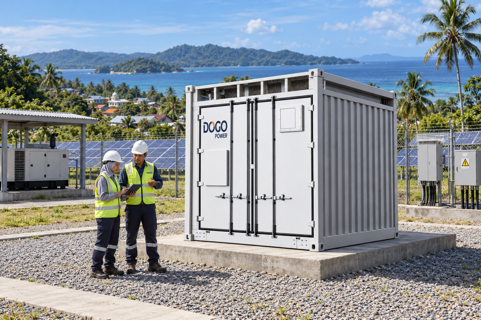
We designed the DG2000-2508kWh as a 10ft Versatile ESS for grid-forming applications. The DG2000-2508kWh-2H0 configuration has a rated capacity of 2,508 kWh, uses LFP/314 Ah batteries, and features dual liquid cooling for the battery packs and PCS.
Its 10ft design supports intermodal transport as a standard 20ft container and single or combined lifting. Plug-and-play connections and a design that avoids underground cable trenching help simplify on-site construction.
The system's dynamic C-rate architecture supports flexible expansion and backup durations from 2 to 8 hours, depending on the system configuration. Its three-layer grid-forming control architecture brings together dispatch, coordination, and control. Smart O&M functions include solar power forecasting, load forecasting, and intelligent economic dispatch.
Why PCS Is Central to Grid-Forming Energy Storage
A power conversion system is the point where stored battery energy becomes controllable AC power. Its bidirectional conversion supports charging and discharging; its control functions influence efficiency, voltage, frequency, and power quality; and its grid-forming capability can help an energy storage system create a stable local electrical reference.
For a strong-grid project focused on peak shaving or energy shifting, a grid-following PCS may meet the operating objective. For a weak-grid, off-grid, microgrid, or renewable-dominated application, the evaluation should move toward verified grid-forming capability and coordinated control across the complete BESS.
DoGo Power’s GFM energy storage solutions place PCS inside a broader 4S architecture, connecting fast electrical control with battery protection, plant coordination, and energy management. If you are evaluating PCS for a C&I, utility-scale, or off-grid project, contact DoGo Power to discuss the required operating mode, system configuration, simulation scope, and commissioning plan.
FAQ
Is islanded operation the same as black start for a BESS?
No. Islanded operation keeps a local network running after it separates from the grid, while black start begins energizing a de-energized network from a dead bus. Black start requires a grid-forming PCS, sufficient battery reserve and auxiliary power, support for transformer inrush and motor starting, and a verified restoration sequence.
What should a project team verify before selecting a PCS for a BESS?
Verify the PCS against the project's operating mode, grid conditions, and support requirements. Review its power and voltage range, reactive-power capability, grid-forming functions, BMS/EMS/PMS interfaces, protection and grid-code requirements, simulation scope, remote diagnostics, spare parts, and commissioning support before comparing supplier quotes.
What should be tested before commissioning a grid-forming PCS?
Test the PCS under the operating conditions the project will actually face. Include load steps, PV or diesel coordination, islanding and resynchronization, protection settings, voltage and frequency response, multi-unit power sharing, black-start sequences where required, and communication between the BMS, PCS, EMS, and PMS.
What commonly causes PCS-related downtime after BESS commissioning?
Communication faults and protection trips are common causes. SOC drift, cooling or HVAC issues, nuisance BMS protection, weak alarm handling, limited remote access, and slow spare-parts or service response can also extend outages, so commissioning should include interface tests, alarm review, remote diagnostics, and a clear support plan.


